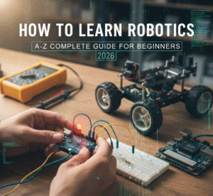
The 2026 Robotics Guide (Part 1): Basic Electronics for Beginners
Table of Contents
Electronics are the basic foundation for modern technology. From the small diodes and transistors to high end level ICs and chips that structured the robots and give them the ability to live a new life, that’s the main core of electronics and in our article, we cover some basic of it and discuss to the point. You are also able to learn where each component to be used and right technique to design a safe circuit from basic to advance.
ACTIVE Components Components include Connectors, Switches and Relays.
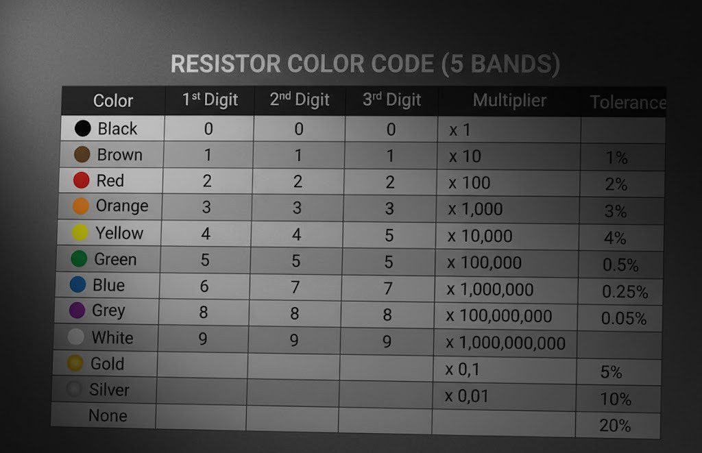
What is Resistor and Its Types
A resistor is defined as two terminal passive element that provides electrical resistance to current flow. Resistance is measure of opposite flow of current in resistor. Resistors are passive elements means those which not provide energy instead it absorbs the energy and release heat after flow of current through the circuit.
It protects against spikes in circuit due to high current flow and prevent circuit from damage. In each bulb or circuit, we need accurate and stable voltage across the component. So, we have to use resistors for creating a proper voltage drop.
SI unit = Ohm ( Ω )
1Ω = 1 Volt/ 1 Ampere
They come in various values like 1mΩ ( 10^-3) , 1KΩ ( 10^3) and 1MΩ ( 10^6 )
PULL UP RESISTOR:
It is a fixed value resistor and need high state(1 ) as default and want the state to low by some external interaction. It allows controlled flow of current from supply voltage like Vcc to digital pin in our MCU.
PULL DOWN:
Pull down resistor is connected with ground, it makes default state as low(0 ) only, no high input only if switch gets on.
let we have circuit, and we have 470 Ω resistor placed un series with LED, so that it limits current flowing into LED. But be sure to use accurate value resistor because too small could burn out the LED and too large could dim the LED.
What is Transistor and Its Types Explained
Transistors allow for controlling the current or voltage flow between two layers by applying electric current to the third layer. It is used in Radios, computer and in ICs.
It mostly used for:
Amplification
Sensor Application
Lighting
Amplification
It has commonly two types:
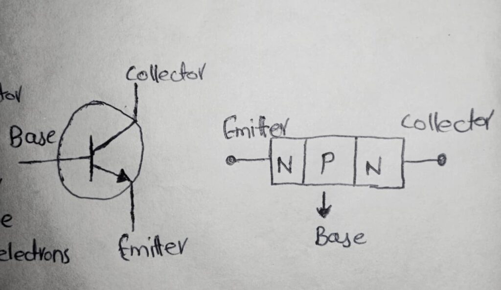
1. NPN TRANSISTOR:
It consists of three semiconductor layers. In NPN, electrons carry current in N-Type regions via holes while the majority carriers in P-Type region also play a role. Its function is to regulate the movement of current between its emitters (electron source), base(current regulator) and collector(electron receiver).
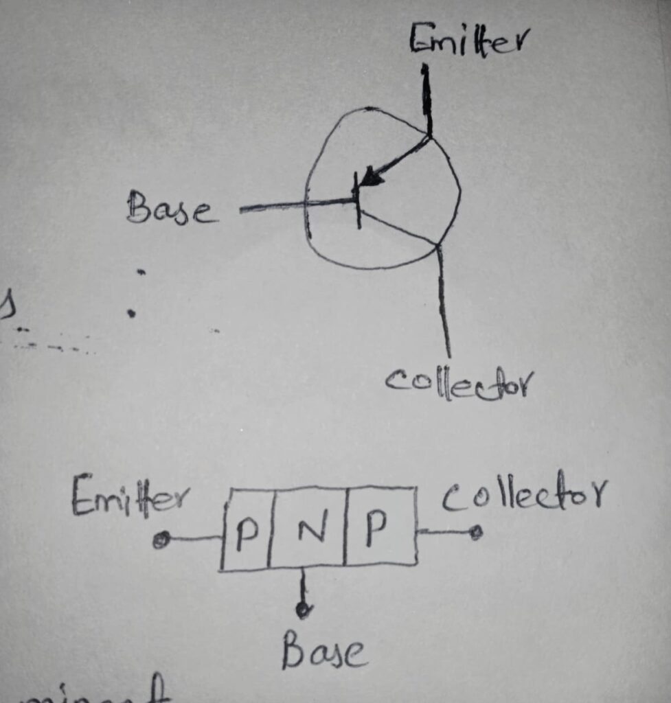
2. PNP TRANSISTOR:
It’s a form of bi-polar junction that compromises up to three layers of semiconductor material; it features a thin layer of N-type semiconductor in between two layers of P-type. In PNP, transistor can act as resistor and transfer means in transistor a signal is introduced in a low resistance circuit, and an output is taken high. Its location is in between your LED and ground (common emitter). The transistor act as a switch.
Avoid attaching base of transistor from high voltage without any resistor in it.
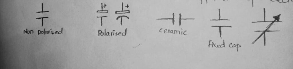
What is Capacitor and Its Types Explained
A capacitor is characterized by its capacity to store charge. It’s a passive component that stores energy in its field that are pairs of conductors called “plates”.
POLARIZED CAPACITOR
NON-POLARIZED CAPACITOR
SI unit of capacitance is Farad (F). A one Farad capacitor, when charged with 1 coulomb of electric charge, has a potential difference of 1V between its plate.
ITS TYPES INCLUDE:
ELECTROLYTIC CAPACITOR:
These are used where large capacitance is needed. Anode of this capacitor is made of metal and is covered with oxidized layer that used an di-electric.
VARIABLE CAPACITOR:
It’s a non-polarized type of capacitor. They have moving and fixed plates for determining the capacitance. They are generally used in Transmitter, receivers and in Radios.
CERAMIC CAPACITOR:
It’s a most common and cheaper to manufacture capacitor. These are excellent di-electric because of its poor conductivity and excellent supporting of electrostatic.
PURPOSE IN CIRCUIT:
It helps to filter noise, stabilize voltage when powered and when on base it delays switching like Fade In/Fade Out.
TIP: Must use 0.1uF ceramic capacitor in parallel with large capacitor to filter high frequency noise.
What is Inductor ?
Inductor is a passive circuit element that can store electrical energy in form of magnetic field. The most important is that it opposes any change in amount and direction of current flowing through it means the current flowing through inductor couldn’t suddenly change. It reduces noise spike from transistor switching and it store energy when current flow and then it reduces it. Avoid using it with too high resistance or with low current rating.
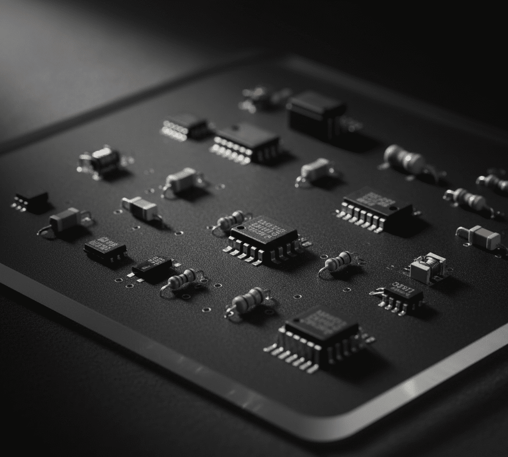
Difference between SMD and THT components
SMD(Surface Mount Device) Components are the backbone of modern PCBA that mounted directly onto the surface of PCB using SMT (Surface Mount Technology). It mostly comes in higher density, better high frequency and can be used in fully automated products. THT Components comes in comparison of SMD and in both cases SMD wins because of its light weight, small size, more compatible and easier to manufacture.
For simple Arduino or sensors-based projects mostly preferable is 9V or AA battery. For high performance use Li-ion(18650) or LiPo cells with protection circuit.
Voltage is push of electricity while current is flow of electrons. Too much voltage can damage components and too much current can stop circuit from working.


Great Post