Build a Drone with APM 2.8 – With Pictures & Wiring Full Setup – Guide 2025
Why Build a Drone with APM 2.8? Project Goals
Building a drone with APM 2.8 flight controller which can be useful in many sectors like agriculture,
photography, specelized missions etc.
Step-by-Step Quadcopter Build Plan
| Phase | Details |
|---|---|
| Phase 1: Components & Assembly | Components purchased and assembled, ensuring all parts are ready. |
| Phase 2: Programming & Calibration | Drone programmed, tuning completed for flight controller, sensors, and GPS. |
| Phase 3: Testing & Optimization | Testing performed, with necessary adjustments and optimizations for best performance. |
Table of Contents
- 1. Installation
- Flight Controller & Receiver Setup
- Modules Integration
- 2. Programming & Calibration
- Software & Firmware Setup
- Mission Planner Installation
- APM 2.8 Firmware Upload
- Calibration & Configuration
- Accelerometer Calibration
- Compass Calibration
- Radio Calibration
- Flight Modes Setup
- Remote Controller Setup
- Software & Firmware Setup
- 3. Testing & Optimization
- Initial Flight Testing
- Pre-Flight Checklist
- Battery Charging & Discharging
- Initial Flight Testing
- 4. Conclusion
- Summary of Achievements
- 5. References & Appendix
- Datasheets & Technical Resources
1.INTRODUCTION
Project Overview
This project is about building a quadcopter drone with APM 2.8 flight controller as the main control unit. There are many other flight controllers available in the market, but we chose APM 2.8 for specific reasons, which we’ll discuss later in upcoming articles. For now, let’s go through an overview of the project.
A quadcopter drone is a powerful project for various guided missions, such as firefighting, surveillance in areas where humans cannot easily go or survive (like deep forests and high mountains), and other tasks like photography, recreational flying, and more. Its versatility makes it useful for both professional and hobbyist applications.
In the upcoming sections, we will explore the step-by-step process of building this amazing drone and getting it up and flying. We discuss everything from assembling the components to testing the drone stability. Commonly we face a lot of issues while building quadcopter drone with apm2.8 I have discussed the issues here in this article
Phase 1: Components & Assembly
2. HARDWARE COMPONENTS
In this section and phase we will discuss about what
componets we used and how to assemble them.
APM 2.8 Drone Parts List & Components
- Flight Controller: APM 2.8
- Motors & Propellers:
- Brushless Motors: 1000KV (4x)
- Propellers: 1045 inches (4x)
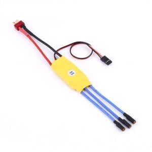
- Electronic Speed Controllers (ESCs):
- ESCs: 30A (4x) (For Buying its comes with Motors, link is provided)
- Power System:
- Battery: 3300mAh LiPo (3S)
- Power Module for APM
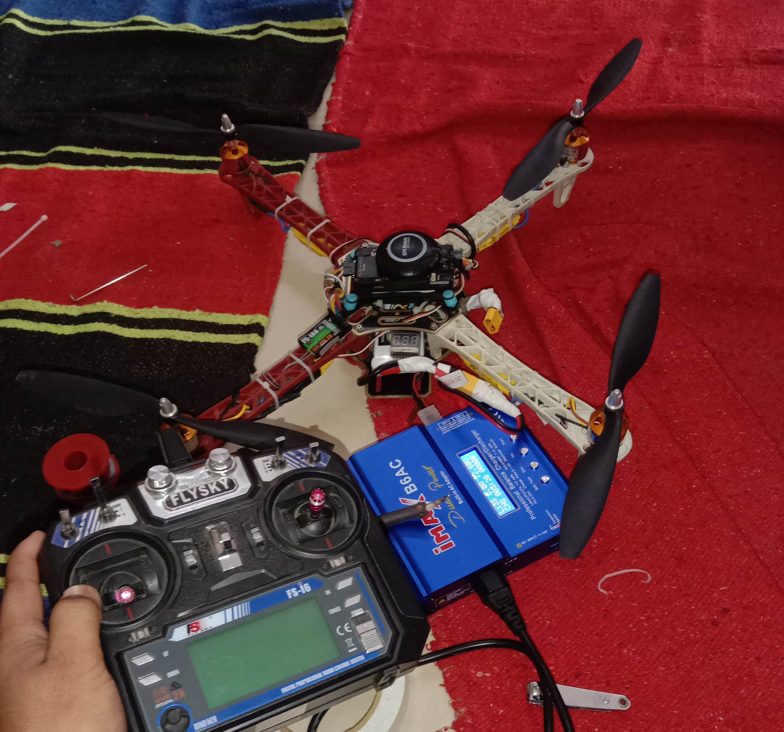
- Charger: IMAX b6AC
- Radio Control System:
- Transmitter: FlySky FS-i6
- Receiver: FlySky FS-iA6B
- GPS:
- GPS Module: M8N (For Buying: Already included in APM2.8 Kit)
- Frame & Structure:
- Frame: F450 Quadcopter Frame.
- Zip Ties
- Shock Absorber: For APM2.8
3. Building the Drone - Frame, Motors, ESC & More
Motor & ESC Installation Guide for Quadcopter Drone
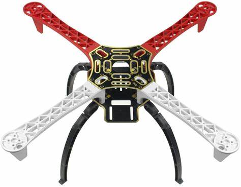
- Take the F450 quadcopter frame and attach the four arms to the main PCB board using screws.
- Ensure all arms are firmly secured for stability.
- Locate the soldering pads on the PCB board.
- Apply solder to all designated motor power connection points.
- Take the four ESCs and solder them one by one to the PCB board.
- Connect the positive (+) wire of each ESC to the positive (+) pad on the PCB.
- Connect the negative (-) wire of each ESC to the negative (-) pad on the PCB.
- Each ESC has three output wires for the motor and three input wires for power and signal.
- The two outer wires of the ESC input connector are positive (+) and negative (-).
- If the outer wires are swapped, the motor’s rotation will change (clockwise or counterclockwise).
- The center wire is the signal wire, which will be connected to the flight controller later.
- Take each ESC and connect its three output wires to the three input wires of the corresponding motor.
- Match the left wire of the ESC with the left wire of the motor and the right wire of the ESC with the right wire of the motor.
- Connect the center wire of the ESC to the center wire of the motor.
- Repeat this process for all four motors and ESCs.
- Since motor direction can be adjusted later, the initial connection order does not have to be exact.
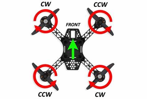

Make sure to follow the correct motor rotation pattern, as shown in the reference picture. The forward direction of your drone should also match the orientation in the image. If any motor is spinning in the wrong direction, you can easily fix it by swapping the left and right wires of the ESC connected to that motor. This will reverse its direction and ensure proper flight stability.
APM 2.8 Flight Controller Guide & fs-i6 Transmitter & Receiver Setup
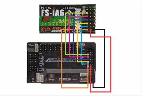
After completing the ESC and motor connections, the next step is to mount the APM 2.8 on the F450 frame. It is crucial to position the flight controller precisely at the center of the drone, as even a slight deviation can cause instability during flight. Secure the APM using zip ties to ensure it remains firmly in place. To minimize vibrations, avoid attaching the APM directly to the frame. Instead, first install a shock absorber and secure it with zip ties. Then, use double-sided tape to mount the APM on top of the shock absorber. This setup helps reduce vibrations reaching the flight controller, improving stability and flight performance. Flight Controller & Receiver Setup Now, take the receiver, which will be using 6 channels for control. The receiver has three rows of pins

Top row → Signal pins
Middle row → 5V (+) power pins
Bottom row → GND (-) ground pins
Next, take the output wires of the ESCs, which consist of signal, 5V, and GND wires, and connect them to the outputs of APM 2.8 and do for all same as this. NOW connect APM input to Channel 1 of the receiver, and repeat this for all four inputs of APM to 4 inputs of receiver, ensuring the correct channel assignment for proper control.

How to Connect GPS module M8N with APM 2.8 Circuit
- Take the GPS module and connect one set of its wires to the GPS port on the APM 2.8 flight controller (it will be labeled as “GPS”).
- Connect the other set of wires to the port located directly below the GPS port. This second port is used for the compass module that comes with the GPS unit.
- Ensuring proper connection of both sets of wires is essential for accurate navigation and positioning.
- Now, solder the Power Module to the PCB board, as it will be the main power source for the drone.
- Solder the positive (+) and negative (-) terminals of the Power Module to the corresponding points on the PCB board.
- On the output side of the Power Module:
- Take the set of output wires and connect them to the PM (Power Module) port of the APM 2.8 flight controller.
- Another output wire from the Power Module will be connected to the battery, but do not connect it yet. We will attach the battery later when everything is properly set up.
Phase 2: Programming & Calibration
4. Install APM 2.8 Firmware & Mission Planner Setup
In this phase we will discuss how to download and
install the software and upload the firmware in APM2.8
How to Install Mission Planner Software for apm2.8
1. Open your favourite browser and search “Mission Planner Software Download”, and click on the official link of ArduPilot website.
2. And then follow the instructions on website and download the software in your pc.
How to Upload APM 2.8 Firmware to Flight Controller
1. Connect APM 2.8 to Your PC: Use a USB cable to connect the APM 2.8 flight controller to your computer.
2. Select COM Port & Baud Rate: In the top-right corner, select the correct COM Port (e.g., COM3, COM4, etc.). Set the Baud Rate to 115200.
3. Go to the “Install Firmware” Section: Click on “Initial Setup” → “Install Firmware”. Select Quadcopter (latest APM 2.8 supported version).”
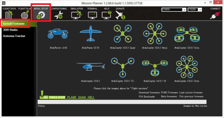
4. Load & Install Firmware: Click on “Load Firmware”, then “Upload Firmware”. Mission Planner will erase old firmware and upload the new one. Wait for the progress bar to complete.
5. Firmware Upload Successful: Once the firmware is uploaded, Mission Planner will show “Firmware successfully uploaded”. Disconnect and reconnect APM 2.8 to restart it.
6. Perform Initial Setup: Go to “Initial Setup” → “Wizard” and follow calibration steps we will discuss later on this report.
5. APM 2.8 Calibration, Compass, Flight Modes & Radio Calibration
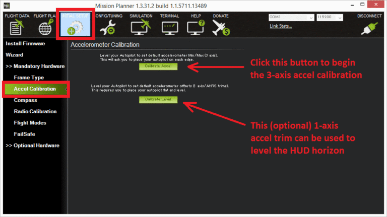
APM 2.8 Accel Calibration
1.Confirm that APM is connected to your PC, and COM port is selected.
2. Mission Planner will ask you to place the quadcopter in six different orientations and press “Done” after each step:
- Level: Keep the drone flat on a table.
- On Right Side: Rotate and place it on the right side.
- On Left Side: Rotate and place it on the left side.
- Nose Down: Tilt it forward (nose pointing down).
- Nose Up: Tilt it backward (nose pointing up).
- Upside Down: Flip it completely upside down.
- Press “Done” after placing it in each position.
- Now, after doing accelerometer calibration, click on “Done” calibration.
Compass Calibration for APM 2.8
- Enable External Compass (If Used): Go to “Initial Setup” → “Mandatory Hardware” and then “Compass”. Check the option “Use Compass #2 (External Compass)”.
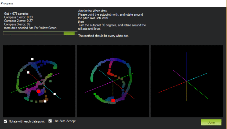
- Start Compass Calibration: Click “Start” under “Live Calibration”. Rotate the quadcopter smoothly in all directions:
- Yaw: Spin it left & right.
- Pitch: Tilt it forward & backward.
- Roll: Turn it sideways left & right.
Continue rotating until all dots turn green on the screen.
- Save Calibration Data: When all dots are green, click on “Done” button. If successful, Mission Planner will automatically show “Calibration Successful”.
Radio Calibration for fs-i6 transmitter & APM2.8
- Turn ON the Transmitter: Power ON your Fly Sky FS-i6 transmitter. Ensure the receiver (FS-iA6B) is properly bound with the transmitter (Red LED on the receiver should be solid/static).
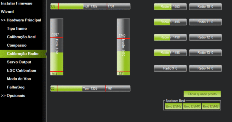
- Open Radio Calibration Window: Go to “Initial Setup” → “Mandatory Hardware” → “Radio Calibration”. Click “Calibrate Radio”.
- Move the Sticks & Switches: Move both joysticks in all directions:
- Throttle: Left Stick Up/Down
- Yaw: Left Stick Left/Right
- Pitch: Right Stick Up/Down
- Roll: Right Stick Left/Right
- Toggle any switches: (if used for flight modes or auxiliary functions).
You should see green bars moving on the screen.
- Set Min & Max Values: Ensure all sticks reach their full range (1000-2000 PWM). Move the sticks and ensure the quadcopter responds correctly.
- Save Calibration: Click “Done” when finished. Mission Planner will save the calibration settings.
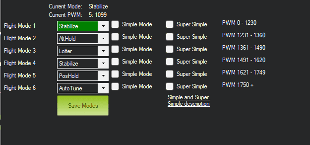
How to setup Flight Modes in Mission Planner for APM2.8
1. Open Flight Modes Setup Go to “Initial Setup” → “Mandatory Hardware” and
then “Flight Modes”. You will see six flight mode slots, which
correspond to your transmitter switch positions. (auxiliary switches, you can assign every switch to specific flight mode, we will discuss this function later in upcoming articles)
2. Select Flight Modes Choose flight modes based on your skill level and requirements. Commonly used modes are:
| Mode | Description |
|---|---|
| Stabilize | Manual control with auto-leveling. Good for beginners. |
| AltHold | Maintains altitude automatically but allows movement. |
| Loiter | Holds position using GPS (Requires M8N GPS). |
| RTL (Return to Launch) | Holds position using GPS (Requires M8N GPS). |
| Auto | Follows a pre-programmed mission. |
| Acro | Full manual control (for advanced users). |
Remote Controller Setup
Move your transmitter’s flight mode switch to each position. Observe the highlighted PWM value in Mission Planner. Assign different modes to each switch position by selecting them from the dropdown menu. ( (auxiliary switches, you can assign every switch to specific flight mode, we will discuss this function later in upcoming articles))
How to do ESC Calibration for APM2.8 Quadcopter
It is important to calibrate the ESC’s before flying.
Sometimes, the motors do not produce beep sounds,
so do not solely rely on them. Follow these steps:
- Disconnect the battery from the drone.
- Move the throttle stick on the remote to the highest position.
- Reconnect the battery to the drone and observe the APM lights.
- When red and blue lights on the APM start blinking, unplug the battery again.
- Reconnect the battery, and when the red and blue lights start blinking again, immediately move the throttle stick to low.
- After 2-3 seconds, gradually increase the throttle.
- If all motors start at the same time, the ESC’s are calibrated.
- Unplug the battery and replug it to exit calibration mode.
Propeller Mounting
Phase 3: Testing & Optimization
In this phase we will discuss some pre flight checks and
how to fly drone safely morover we will talk about
battery charging and discharging.
6. Quadcopter Pre-Flight Checklist & First Flight Test
Pre-Flight Checklist
- Before flying, please go through this checklist: Check Battery Voltage Refer to the provided battery voltage table. Ensure the battery voltage monitoring module is connected, so you receive beep sound when the battery is low.
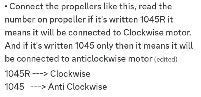
- Verify Propeller Orientation Check that the propellers are installed correctly, following the clockwise (CW) and counterclockwise (CCW) according to each motor refer to the provided way to connect propellers
- Inspect Wiring & Connections Ensure all wires are connected tight, especially the receiver’s 5V and GND wires on drone, because they are always loose so consider them especially.
- Inspect Wiring & Connections Ensure all wires are connected tight, especially the receiver’s 5V and GND wires on drone, because they are always loose so consider them especially.
- Check APM Arrow Direction ⬆ Before flying keep in mind that the forward direction of apm should be towards you, I mean that the arrow of apm or gps should be towards you then drone will correctly fly if the direction of apm arrow is opposite from you then it will not fly correctly. (It’s my personal test and opinion in your case it can vary or maybe different)
- Ensure All Screws Are Tight Check and tighten all screws on the quadcopter frame and components.
7. Safe LiPo Battery Charging & Discharging for Drones
Charging and Discharging a 3S 3300mAh 30C LiPo
Battery Using IMAX B6 AC Charger
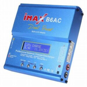
How to Charge LiPo Batteries for Quadcopters Drones
- Connect the Charger
- Plug in the IMAX B6 AC charger to a power source.
- Ensure the charger is on a non-flammable surface.
- Connect the Battery
- Connect the main battery lead (XT60 or any connector you want to use) to the charger’s output port.
- Connect the balance plug (JST) to the charger’s balance port.
- Select Charging Mode
- Turn on the charger and go to “LiPo Balance Charge” mode.
- Set the charging current to 3.3A (1C rule → Battery Capacity ÷ 1000).
- Ensure the voltage is set to 11.1V (3S).
- Start Charging
- Press and hold the Start button.
- The charger will check the battery and confirm settings.
- Press Start again to start the charging.
- Monitor the Charging Process
- The charger will display voltage per cell and total charge time.
- Charging is complete when the screen shows “FULL” or 4.2V per cell (12.6V total for 3S).
Discharging LiPo Safely After Drone Flight
- If the battery is not in use for a long time, discharge it to storage voltage (3.80V per cell, ~11.4V total).
- Select Discharge Mode
- On the charger, select “LiPo Discharge” mode.
- Set the discharge current to 1.0A.
- Set the cut-off voltage to 11.4V (3.8V per cell).
- Start Discharging
- Hold Start, confirm settings, and begin the discharge process.
- Once complete, the battery is at safe storage voltage.

Precautions When Handling LiPo Batteries
| DO’s | DON’Ts |
|---|---|
| Always balance charge the battery. | Never charge above 4.2V per cell (Overcharging can cause fire). |
| Charge on a fireproof surface (e.g., LiPo safety bag). | Never discharge below 3.0V per cell (Over-discharge damages battery). |
| Use a LiPo alarm to monitor voltage during flight. | Don’t puncture, crush, or expose to heat or water. |
| Store at room temperature and at storage voltage (3.8V per cell). | Don’t leave the battery unattended while charging. |
| Inspect for swelling, damage, or overheating before and after use. |
8. CONCLUSION
Recap of the DIY APM 2.8 Drone Project Guide
Once the wiring was completed, we provided a detailed guide on downloading and uploading firmware to the APM, making sure that every step is clearly explained to minimize potential errors and ensure smooth operation. After completing the wiring and firmware installation, we moved on to the calibration process, covering accelerometer, compass, and radio calibration in detail to ensure precise and stable flight performance. Following radio calibration, we proceeded with the ESC calibration, ensuring that all motors respond correctly and uniformly to throttle inputs. Additionally, battery guidance was discussed thoroughly, including proper charging and discharging procedures to prevent potential hazards and extend battery life. Finally, we covered the Pre-Flight Checks, ensuring that every component is properly configured and functioning before takeoff, minimizing risks and enhancing flight safety.
9. References & Technical Resources for Drone Builders
Datasheets, Manuals & Firmware Links
https://componentsexplorer.com/apm-2-8-flight-controller-datasheet
https://discuss.ardupilot.org/t/apm-2-8-and-mission-planner/81319
https://ardupilot.org/
https://firmware.ardupilot.org/Copter/
https://ardupilot.org/ardupilot/
https://thinkrobotics.com/blogs/learn/f650-vs-f450-vs-f250-5-key differences-between-drone-frames-that will-save-you-in-your-next-build
https://ardupilot.org/planner/
https://www.electrical4u.com/brushless-dc-motors/
https://www.instructables.com/APM-Quadcopter-Setup/
https://quadcopterforum.com/threads/apm2-8-quad-build-issues.11818/
https://youtu.be/eSCvCAC7Q-c
https://youtu.be/Z-8vvT7zC5U
https://youtu.be/JMSwDUrns2Q
https://www.youtube.com/embed/9AbijdRNC6Q? feature=oembed&autoplay=1

SHARE WITH YOUR FRIENDS

Awesome 👌
Thank you 🙂
Good Information and nice work
Great to hear 🙂 Stay Tuned for Amazing Stuff Coming up