Ultimate Guide 8051 Microcontroller Architecture, Features & Circuit Diagram
Table of Contents
What is the 8051 microcontroller?
Introduction
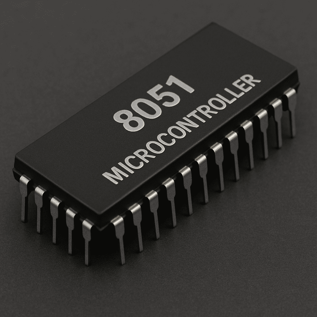
8051 also written as MCS-51. 8051 is 8bit microcontroller which means it can process 8-bits of data at a time. 8051 microcontroller has multiple variants and most used one is AT89C51, the ‘C’ means it is based on CMOS technology. Let’s discuss its history first then we’ll move to 8051 microcontroller architecture and features.
Brief History of 8051
The first processor was invented by Intel Corporation “4004”, People called it a New Era of Integrated Electronics, similarly later other microcontrollers were invented like 8085, 8086 and in 1981, Intel introduced an 8051 microcontroller. It became very popular and still now it is used by many. 8051 is also known as MCS-51 in more technical terms.
Now let’s dive deeper into 8051.
Overview of 8051 Microcontroller
A microcontroller is like a tiny system that has some features of computer designed for specific tasks, useful to build electronic systems and control machines.
Similarly, 8051 is prime example of such microcontroller.
Specifications & Features of
8051 microcontroller
Specifications and features of 8051 microcontroller is discussed below:
- 8051 micro-controller consists of 128bytes of RAM
- 4096 bytes of storage to store the program.
- Crystal oscillator of 12MHz commonly for accurate time keeping and some functionalities like delay.
- 32 I/O Pins arranged as four 8bit ports
- Two 16-bit 8051 Timers/Counters
- Supports Serial Communication (UART).
- Can access external RAM & ROM in case of limited memory
- Low Power Consumption (Different power down modes)
- Boolean processing
- Five interrupt sources (Two external, two timers and one serial.)
- Cost Efficient
Due to budget friendly and core hardware for embedded systems, many students and tech enthusiasts prefer 8051 for many tasks.
Most common software’s used with 8051 are Keil (To write a firmware and get output as hex file) and Porteous (For Real-Time Simulation) of 8051.
MCS-51 can be programmed in 2 programming languages, C or Assembly, programmer can choose the language with which they are comfortable with.
8051 Microcontroller Architecture
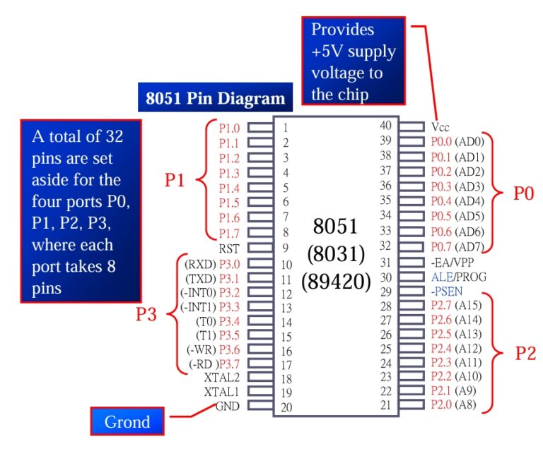
Pin Diagram of 8051
Here is Schematic Diagram of 8051 microcontroller shown in detail
Components of 8051 microcontroller
CPU
The MCS-51 Microcontroller has 8-bit CPU (Central Processing Unit). It means 8051 can process, send, receive 8bits of data at a time. It can handle operations like Addition, Subtraction & Logical tasks using 8bit registers and data bus.
RAM/ROM
RAM: 8051 has 128 bytes of total RAM available to perform operations for program execution. It can be extendable in case your project needs more RAM for specific project.
ROM: The MCS-51 Microcontroller has 4KB of Storage/ROM which enables microcontroller to store the code and other important dependencies related to project permanently until reprogrammed, the storage of MCU will not be erased if you power off it, as this memory is non-volatile.
Timers/Counters
The 8051 has two timers/counters they can be used to generate a time delay in system or as event counter, there are total 2 timers/counters in 8051, known as Timer 0 & Timer 1, both are 16bits wide but as 8051 is 8bit microcontroller that’s why these 16bits timer/counter are divided into 8-8 bit chunks and they can be accessed by LOW & HIGH Byte (TH0 & TL0).
Most commonly timers are most used feature in MCS-51 as they generate time delays in system.
Time Delays can be generated via 2 ways:
- Using for-loops: This method is easy to implement but not gives precise and accurate time delay because for-loop itself takes some time in millisecond to execute. In some systems where little variation of milliseconds is very impactful, there for-loop way is not used. Example of that system is Clock (If after every second some milliseconds are delayed then after 24-48 hours the big change in time can be seen, it can be up to 1hour delayed compared to original GMT).
- Using Timers for Time Delay: Using timers for time generation is best and recommended approach as it works on crystal frequency and gives accurate time for delay generation.
We can setup our delay function like this (Here only overview is given we will discuss this topic in upcoming articles)
8051 Timer Modes
| Timer Mode | Mode Number | Description |
|---|---|---|
| 13-bit Timer Mode | Mode 0 | Uses lower 5 bits of TH and all 8 bits of TL. |
| 16-bit Timer Mode | Mode 1 | Uses all 16 bits of TH and TL for timing. |
| 8-bit Auto-Reload Mode | Mode 2 | Reloads TH to TL automatically after overflow. |
| Split Timer Mode | Mode 3 | Splits Timer 0 into two 8bit timers. |
- First choose the mode of timer. Choose the mode from table and put it in code like
TMOD = 0x01 // (Timer 0 Mode 1)
- Then calculate the values which you will use for TH0 and TL0, it’s your choice you can choose Timer1 also and put that into code (It should be in HEX format) like this
TH0 = 0xFC; // (for 1ms delay using 12MHz crystal oscillator), TL0 = 0x66;
- Then start the timer using
TR0 = 1;
- Once timer is started set the overflow flag
TF0 = 1
And monitor it using while condition.
while (TF0 == 0);
- First choose the mode of timer. Choose the mode from table and put it in code like
By following these steps, we can generate 1ms of accurate delay similarly to generate 1 second of delay just calculate the TH and TL values for 1sec and put that in code and use while condition inside delay function to generate 1 sec of delay.
Here is an example code to generate 1second of delay using timers.
					// Written by SHAH_ZAMAN_HAIDER
// Visit https://robetix.com for more projects and updates

#include <reg51.h>

void delay_1s();

void main() {

        delay_1s(); //  for more delay just put a loop.
}

void delay_1s() {
    TMOD = 0x01;
    TH0 = 0xFC;
    TL0 = 0x18;
    TR0 = 1;
    while (TF0 == 0);
    TR0 = 0;
    TF0 = 0;
}
8051 I/O Ports
8051 micro controller has 4 Input/Output ports. These are all 8-bit ports and has 8 pins for each port to perform I/O operations.
Pins of 8051 is written or pronounced as P1^2, P2^3 etc. Port is mentioned first and then pin number is written with bitwise operator to clarify which port and pin we are working on.
By default, all pins are for input operations on RESET but if you want output operations, just write that pin address like P1_2 and give it a value 1 which means it will now act as output.
× For Input Assign 0 or 0xFF
× For Output Assign 1 or 0x00
All pins can work without any resistor but P0 has different case, put 10K ohm pull-up resistor to that pin of Port 0 which you want to work on because Port 0 is open drain.
Port 0 is used for I/O, Data and Address
Port 1 is also used for I/O, and it doesn’t require any pullup resistor since it already has pullup resistors internally.
Port 2 is also used for I/O, and it doesn’t require any pullup resistor since it already has pullup resistors internally.
Port 3 is same as Port 1 & 2, but it has additional functions which makes it unique like Rx, Tx, INT0, INT1, etc.
Serial Port
Serial Port is one of the ports of 8051 which enables communication between different sensors and devices with 8051, communication happens serially means sending and receiving happens one bit at time.
Pin 0 (RXD) and pin 1 (TXD) of Port 3 are used for Serial communication in 8051.
Where,
× RXD (Receive Data)
× TXD (Transmit Data)
To enable Serial communication Serial Control Register comes to action (SCON).
And the rate of data transfer in Serial communication is usually stated in bps (Bits Per Second) or Baud Rate.
Baud Rate is most used term in Embedded Systems which means the rate of data transfer in Serial communication.
Now to send data, it is placed inside SBUF register, SBUF is an 8bit register that acts like a temporary container before sending it to TXD line.
SCON is a register to program the Start and Stop bits and frame the data for communication.
There are two flags to indicate data sent or received, TI (sent) and RI (received). These 2 flags are raised that indicates that previous data is sent or received and is ready for new data.
By Checking these two flags we can know whether 8051 is ready for another transfer or not.
Here is a basic example code to send “HELLO” via Serial Communication
					// Written by SHAH_ZAMAN_HAIDER
// Visit https://robetix.com for more projects and updates

#include <reg51.h>

void main() {
    TMOD = 0x20;
    TH1 = 0xFD;   // 9600 baud rate
    SCON = 0x50;
    TR1 = 1;

    while (1) {
        SBUF = 'H';
        while (!TI);
        TI = 0;

        SBUF = 'E';
        while (!TI);
        TI = 0;

        SBUF = 'L';
        while (!TI);
        TI = 0;

        SBUF = 'L';
        while (!TI);
        TI = 0;

        SBUF = 'O';
        while (!TI);
        TI = 0;
    }
}
Here is a basic example code to receive “HELLO” via Serial Communication
					// Written by SHAH_ZAMAN_HAIDER
// Visit https://robetix.com for more projects and updates

#include <reg51.h>

void main() {
    TMOD = 0x20;
    TH1 = 0xFD; // 9600 baud rate
    SCON = 0x50;
    TR1 = 1;

    while (1) {
        while (!RI);
        char received_char = SBUF;
        RI = 0;


        if (received_char == 'H') {
            P1 = ~P1;  //toggle P1 if reeived character is H
                       //Do this for other characters also
        }
    }
}
Interrupts
Interrupt in 8051 microcontroller is a signal that pauses the current execution of task and transfer the control to another task for which interrupt is created, completes it and goes back to previous task and resume the main program.
Here is flow of Interrupt which it follows:
- Interrupt request occur
- 8051 stops current executing program
- Jumps to requested ISR address or interrupt location
- Executes ISR (code for which interrupt is created)
- Returns to main program.
MCS-51 has total 5 interrupt sources from which two external hardware interrupts on P3_2 and P3_3, used as INT0 & INT1. Similarly, two are timer and one is Serial port interrupt.
8051 Microcontroller Pinout
Pin Functions
Pin 1-8 (P1.0 – P1.7):
General-purpose I/O pins.
Pin 9 (RST):
Reset pin to initialize the microcontroller.
Pin 10-17 (P3.0 – P3.7):
General-purpose I/O pins + Special Functions.
Pin 18-19 (XTAL1, XTAL2):
Crystal oscillator connections.
Pin 20 (GND):
Ground pin.
Pin 21-28 (P2.0 – P2.7):
General-purpose I/O or address pins.
Pin 29 (PSEN):
Program store enable for external memory.
Pin 30 (ALE):
Address latch enable for external memory.
Pin 31 (EA):
External access enable.
Pin 32-39 (P0.0 – P0.7):
General-purpose I/O or data/address pins. (10k ohm external pull-up resistors required with each pin)
Pin 40 (VCC):
Supply voltage pin.
8051 Microcontroller Programming
8051 microcontroller uses C and Assembly programming language. It depends on programmer to choose C or Assembly according to interest, both languages can work fine in 8051 micro controller.
C is easier to understand and work on that’s why most of beginners prefer C language to work on MCS-51 even professionals also use C. But using C language can increase the code size and can result in larger HEX file.
C data types also have a major role in size of code file, by using appropriate datatype for specific data is very important to keep the size of code small.
Most common and used data types in 8051 (Keil Software) are:
- bit
- sbit
- data
- idata
- xdata
- code
- char
- sfr
- float
- long
- int
C compilers use signed char by default, if not used unsigned
Tools and software for 8051 Microcontroller
To write a program for 8051 microcontroller, the best software is used is “Keil” it is an IDE which enables developers to write firmware for many types of microcontrollers and 8051 is one of them.
To upload the code into 8051, burner is required, without burner program can’t be uploaded into controller.
Similarly, to do simulation of project which involves MCS-51 or any type of microcontroller, “Proteus” software is used mostly to do simulation and view the working of project by selecting the HEX file provided by Keil Software of specific program/project.
This HEX file can be modified later by just editing the code in Keil and generating the updated HEX file.
LED blinking code in 8051 Microcontroller
					// Written by SHAH_ZAMAN_HAIDER
// Visit https://robetix.com for more projects and updates

#include <reg51.h>

sbit LED = P1^2;

void main() {
    while (1) {
        LED = 1;
        for (unsigned int i = 0; i < 50000; i++); // Around 1second delay
        LED = 0;
        for (unsigned int i = 0; i < 50000; i++);
    }
}
Applications of 8051 Microcontroller Projects
Beginner 8051 microcontroller projects examples
- Embedded systems
- Motor speed control
- Washing machines
- Microwave ovens
- Clocks & Timers
- Traffic light control systems
- Digital voltmeters
- Security systems
- Electronic voting machines
- Automatic door control
- Fire alarm systems
Cons/Disadvantages of
8051 Microcontroller
- Limited Memory for program execution
- Less Processing Power to run program
- Limited support for external peripherals
- Special Burner required to burn/upload the code into controller
- Additional components are required to operate the 8051, such as a crystal oscillator.
- Not recommended for complex applications
- No I2C, SPI etc.
Conclusion
So, in short 8051 microcontroller is best platform to get started with Microcontrollers, Embedded Systems. Beginner and newcomers in Embedded Systems are 100% Recommended to learn 8051 and build projects on it especially Timer projects using Timers/Counters.
Once you grasp the concepts, it will build your foundation on Embedded System basics and commonly used terms in this field.
We discussed MCS-51 microcontroller applications in embedded systems and its features like 8051 has 4 ports each port consists of 8pins, and expressed as P1_3, P4_2 etc. This microcontroller has built-in features like timers and counters for precise time keeping, Serial communication for transfer of data with different sensors.
Overall, it has multiple features like this and top choice for beginners and students and even for industries to integrate it into their products in which budget is kept low or even in high end machines for time related tasks.
This is all about overview of 8051 for students and beginners or even professionals to revise their basic concepts.
Drop your thoughts below, even one-word counts!
Take Care Goodbye 🙂
Frequently Asked Questions
8051 also written as MCS-51. 8051 is 8bit microcontroller which means it can process 8-bits of data at a time. 8051 has multiple variants and most used one is AT89C51, the ‘C’ means it is based on CMOS technology.
- 8051 microcontroller consists of 128bytes of RAM
- 4KB of storage to store the program.
- Crystal oscillator of 12MHz
- 32 I/O Pins
- Two 16-bit Timers/Counters
- Supports Serial Communication (UART).
8051 microcontroller uses C and Assembly programming language. It depends on programmer to choose C or Assembly according to interest, both languages can work fine in 8051 micro controller.
To upload the code into 8051, burner is required, without burner program can’t be uploaded into controller.
To write a program for AT89C51 microcontroller, the best software is used is “Keil” it is an IDE which enables developers to write firmware for many types of microcontrollers and 8051 is one of them.

SHARE WITH YOUR FRIENDS

Feel free to share your thoughts